A Mutable Log
A blog by Devendra Tewari
Project maintained by tewarid Hosted on GitHub Pages — Theme by mattgraham
Using a PC based Logic Analyzer
PC based Logic Analyzers (LAs) allow studying signals in digital circuits. These LAs sample the circuit under study at frequencies that vary from 1 MHz to about 50 MHz, and plot the resulting data as a timing diagram. The software that accompanies the LAs usually allows further analysis of the data, and can interpret busses such as CAN, I2C, I2S, RS-232, and SPI.
There are commercial LAs such as Logic from Saleae (pronounced Say-lee-‘A’), and open source LAs such as the Open Logic Sniffer. These are very capable devices and have varying features.
I’ll use Logic from Saleae to demonstrate how these LAs can be used. In our demonstration, I’ll create a simple C# app that reads a binary file exported by Saleae Logic, and calculates the frequency of a square wave signal under study.
Generating and exporting a waveform
Square wave signals can be generated using oscillator circuits. The use of a 555 timer IC is an easy way to build one. Lab waveform generators, like the one’s from Agilent, can also be used.
I’ll assume you have installed the latest version of the Saleae Logic software, currently at version 1.1.4. This is a multi-platform version and runs on Linux and Mac OS X, besides Windows. Connect Logic to a PC using an available USB 2.0 port. It is recommended that you have no other USB device connected to the PC, because Logic has a very small buffer and data needs to be retrieved from the device as quickly as possible. At higher sampling rates, buffer overflow is very frequent and this limits the practical rate to 24 MHz or less.
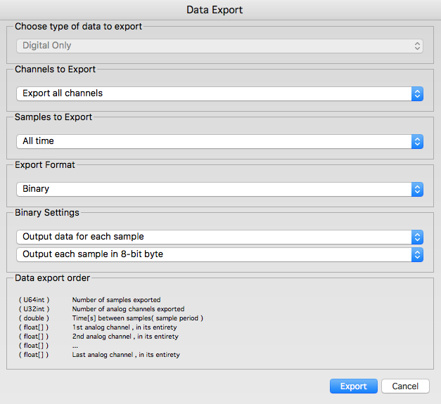
Connect the first input pin (gray wire of the accompanying 8-pin connector) of Logic to the output of the oscillator circuit or waveform generator. In our tests I used a waveform generator producing a square wave at 1 MHz. To accurately measure this signal, Logic needs to sample it at 4 MHz, or more. I used the Logic software at a sampling rate of 8 MHz. Capture about 10 million samples (1.25 seconds of data). Export the data to a binary file at 8-bit byte per sample.
Programming your own analyzer
Here’s a simple C# program that reads the binary file and calculates the frequency of the input signal
uint sampleFreq = 8 * 1000 * 1000;
double averageFreq;
// Skip to a well known point by reading successive transitions.
// Useful for reading clock signals. Skips one clock.
private uint SkipToKnownPoint(byte[] data, uint i)
{
    while ((data[i] & 0x01) == 1)
    {
        i++;
        if (i >= data.Length)
        {
            return 0;
        }
    }
    while ((data[i] & 0x01) == 0)
    {
        i++;
        if (i >= data.Length)
        {
            return 0;
        }
    }
    return i;
}

private void CalculateFrequency(byte[] data)
{
    uint i = 0;
    uint start;
    uint end;
    double avg = 0;
    uint k;
    // skip to a known point
    i = SkipToKnownPoint(data, i);
    if (i == 0)
    {
        return;
    }
    // 9 is arbitrary
    for (k = 0; k < 9; k++)
    {
        start = i;
        i = SkipToKnownPoint(data, i);
        if (i == 0)
        {
            return;
        }
        end = i;
        avg += (end - start);
    }
    avg /= k;
    averageFreq = sampleFreq / avg;
}
SkipToKnownPoint method skips a “square” wave by one clock cycle each time it gets called. CalculateFrequency calls SkipToKnownPoint several times, and calculates the average number of bytes that represent each clock cycle. It then divides the sampling frequency by that value to get the average frequency of the input waveform.
Opening a file and reading binary data from it has been left as an exercise for the reader. Just feed the data as a byte array to the CalculateFrequency method.