A Mutable Log
A blog by Devendra Tewari
Project maintained by tewarid Hosted on GitHub Pages — Theme by mattgraham
I2C with Bus Pirate v4.0 on Windows 10
In this post, I learn to use a Bus Pirate v4.0 to retrieve raw linear acceleration data from a Tilt Compensated Compass Breakout (LSM303DLMTR), over the I2C bus (also referred to as TWI - two wire interface).
I’ve had a Bus Pirate v4.0 for three years now, but it has seen limited use. I’ve never really paused to use it in earnest. I first used it on Windows 8 which had pretty stringent requirements for installing unsigned drivers, that I circumvented using a self-signed driver. Fortunately, Windows 10 does not require any driver installation. The only thing you need to start using the Bus Pirate is terminal emulation software such as Tera Term.
Once you have Tera Term installed and connected to Bus Pirate’s serial port, you can start using the latter’s command line interface to issue commands.
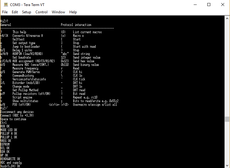
To view help information
HiZ>?
General                                 Protocol interaction
---------------------------------------------------------------------------
?       This help                       (0)     List current macros
=X/|X   Converts X/reverse X            (x)     Macro x
~       Selftest                        [       Start
o       Set output type                 ]       Stop
$       Jump to bootloader              {       Start with read
&/%     Delay 1 us/ms                   }       Stop
a/A/@   AUXPIN (low/HI/READ)            "abc"   Send string
b       Set baudrate                    123     Send integer value
c/C/k/K AUX assignment (A0/CS/A1/A2)    0x123   Send hex value
d/D     Measure ADC (once/CONT.)        0b110   Send binary value
f       Measure frequency               r       Read
g/S     Generate PWM/Servo              /       CLK hi
h       Commandhistory                  \       CLK lo
i       Versioninfo/statusinfo          ^       CLK tick
l/L     Bitorder (msb/LSB)              -       DAT hi
m       Change mode                     _       DAT lo
e       Set Pullup Method               .       DAT read
p/P     Pullup resistors (off/ON)       !       Bit read
s       Script engine                   :       Repeat e.g. r:10
v       Show volts/states               ;       Bits to read/write e.g. 0x55;2
w/W     PSU (off/ON)            <x>/<x= >/<0>   Usermacro x/assign x/list all
To run a self test (connect ADC to +3.3V)
HiZ>~
Disconnect any devices
Connect (ADC to +3.3V)
Space to continue
Ctrl
AUX OK
MODE LED OK
PULLUP H OK
PULLUP L OK
VREG OK
EEPROM
SCL OK
SDA OK
WP OK
READ&WRITE OK
ADC and supply
Vusb(5.03) OK
5V(5.02) OK
5V VPU(4.89) OK
ADC(3.25) OK
3.3V(3.22) OK
3.3V VPU(3.23) OK
Bus high
MOSI OK
CLK OK
MISO OK
CS OK
Bus Hi-Z 0
MOSI OK
CLK OK
MISO OK
CS OK
Bus Hi-Z 1
MOSI OK
CLK OK
MISO OK
CS OK
MODE, VREG, and USB LEDs should be on!
Any key to exit
Found 0 errors.
Use the m command to select I2C mode
HiZ>m
1\. HiZ
2\. 1-WIRE
3\. UART
4\. I2C
5\. SPI
6\. 2WIRE
7\. 3WIRE
8\. KEYB
9\. LCD
10\. PIC
11\. DIO
x. exit(without change)

(1)>4
I2C mode:
1\. Software
2\. Hardware

(1)>2
Set speed:
1\. 100KHz
2\. 400KHz
3\. 1MHz
(1)>1
Ready
Since the breakout is being powered using Bus Pirate, here’s how to disable/enable power output
I2C>w
POWER SUPPLIES OFF
I2C>W
POWER SUPPLIES ON
To check output voltages and I/O state
I2C>v
Pinstates:
#12     #11     #10     #09     #08     #07     #06     #05     #04     #03     #02     #01
GND     5.0V    3.3V    VPU     ADC     AUX2    AUX1    AUX     -       -       SCL     SDA
P       P       P       I       I       I       I       I       I       I       I       I
GND     5.02V   3.28V   0.00V   0.00V   L       L       L       L       L       L       L
To find the address of all devices in the breakout connected to the I2C bus, we can use Bus Pirate’s address search macro. Here’s how you can list all available macros, and run the address search macro
I2C>(0)
0.Macro menu
1.7bit address search
2.I2C sniffer
3.Connect to on-board EEPROM
4.Enable Writing the on-board EEPROM
I2C>(1)
Searching I2C address space. Found devices at:
0x30(0x18 W) 0x31(0x18 R) 0x3C(0x1E W) 0x3D(0x1E R)
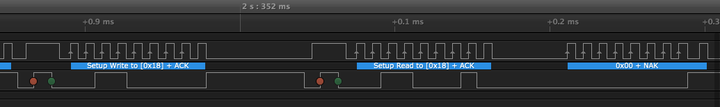
For curiosity’s sake, here’s a partial waveform of the I2C bus when doing address search, analyzed using Saleae’s Logic Analyzer
Now that we know the address of the linear accelerometer (0x18), here’s how we can read register CTRL_REG1_A (note repeated START)
I2C>[0x30 0x20 [ 0x31 r]
I2C START BIT
WRITE: 0x30 ACK
WRITE: 0x20 ACK
I2C START BIT
WRITE: 0x31 ACK
READ: 0x07
NACK
I2C STOP BIT
I configure the breakout to normal (power) mode by writing to register CTRL_REG1_A (address 0x20), and read it back
I2C>[0x30 0x20 0x27]
I2C START BIT
WRITE: 0x30 ACK
WRITE: 0x20 ACK
WRITE: 0x27 ACK
I2C STOP BIT
I2C>[0x30 0x20 [ 0x31 r]
I2C START BIT
WRITE: 0x30 ACK
WRITE: 0x20 ACK
I2C START BIT
WRITE: 0x31 ACK
READ: 0x27
NACK
Here’s how to make use of the autoincrement bit in register address, to read registers STATUS_REG_A (address 0x27) through OUT_Z_H_A (0x2D), in one go
I2C>[0x30 0xa7 [ 0x31 r:7]
I2C START BIT
WRITE: 0x30 ACK
WRITE: 0xA7 ACK
I2C START BIT
WRITE: 0x31 ACK
READ: 0xFF  ACK 0xA0  ACK 0xF9  ACK 0x30  ACK 0x05  ACK 0xF0  ACK 0xC2
NACK
I2C STOP BIT
Read WHO_AM_I_M register (address 0x0F)
I2C>[0x3c 0x0f [ 0x3d r]
I2C START BIT
WRITE: 0x3C ACK
WRITE: 0x0F ACK
I2C START BIT
WRITE: 0x3D ACK
READ: 0x3C
NACK
I2C STOP BIT