A Mutable Log
A blog by Devendra Tewari
Project maintained by tewarid Hosted on GitHub Pages — Theme by mattgraham
Use SPI bus with the 38-pin ESP-32
Synchronous Peripheral Interface aka SPI is a rather fast and flexible serial interface although it is unable to support as many devices per bus as the I2C bus. We’ll explore this bus by interfacing with the commonly available BME680 environmental sensor from Bosch.
Parts
The list of parts we need is rather short
- A 38-Pin ESP-32 Dev Module
- A micro USB data cable to deliver power to and interface with the ESP-32
- A grove BME680 sensor from Seeed Studio
You’ll need to have the Arduino IDE set up and ready to go on your computer.
Wiring Diagram
We’ll wire the sensor to the ESP-32 as follows
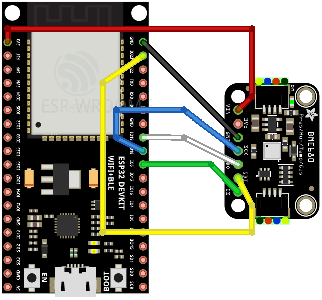
Note that the diagram shows the Adafruit BME680 sensor that is equivalent to the grove BME680 sensor from Seeed Studio.
BME680 grove sensor uses the I2C interface by default. To use the SPI interface, you’ll need to physically sever two traces indicated by I2C and 0x76 labels on the bottom side of the PCB. This can be done by lightly but repeatedly scratching with a pointed cutting tool of some kind.
Configure board in Arduino IDE
Assuming you’ve got the Arduino IDE setup and ready to go, you need to add https://raw.githubusercontent.com/espressif/arduino-esp32/gh-pages/package_esp32_index.json in Additional Boards Manager URLs, in Preferences.
Head over to Tools menu, Board, Board Manager, and install esp32 board support.
Configure Adafruit BME680 library
Head over to the Sketch menu, Include Library, Manage Libraries, and install Adafruit BME680 Library.
Example code
Head over to File menu, Example, Adafruit BME680 Library, and pick bme680test. This will create a new sketch based on bme680test example.
Modify example
The bme680test example is configured to work over the I2C interface by default.
To get it to work over SPI, you’ll need to modify the following lines
Change value of BME_CS to GPIO 5
#define BME_CS 5
Comment creation of I2C interface
//Adafruit_BME680 bme; // I2C
Uncomment creation of SPI hardware interface
Adafruit_BME680 bme(BME_CS); // hardware SPI
Run example
Head over to Tools menu, Board, ESP32 Arduino, and pick board ESP32 Dev Module.
Connect the ESP32 board to your computer, and pick the correct serial port under Tools menu, Port.
Under Sketch menu, select Upload.
Arduino IDE will now build the example code, and wait a while.
Sketch uses 265641 bytes (20%) of program storage space. Maximum is 1310720 bytes.
Global variables use 17496 bytes (5%) of dynamic memory, leaving 310184 bytes for local variables. Maximum is 327680 bytes.

--------------------------
Compilation complete.
esptool.py v3.1
Serial port /dev/cu.usbserial-0001
Connecting........_
Press and hold the BOOT button for a few seconds and release it. After you release the BOOT button, the sketch will be uploaded and run.
Chip is ESP32-D0WDQ6 (revision 1)
Features: WiFi, BT, Dual Core, 240MHz, VRef calibration in efuse, Coding Scheme None
Crystal is 40MHz
MAC: 24:62:ab:f9:02:a8
Uploading stub...
Running stub...
Stub running...
Changing baud rate to 921600
Changed.
Configuring flash size...
Flash will be erased from 0x0000e000 to 0x0000ffff...
Flash will be erased from 0x00001000 to 0x00005fff...
Flash will be erased from 0x00010000 to 0x00050fff...
Flash will be erased from 0x00008000 to 0x00008fff...
Compressed 8192 bytes to 47...
Writing at 0x0000e000... (100 %)
Wrote 8192 bytes (47 compressed) at 0x0000e000 in 0.1 seconds (effective 452.9 kbit/s)...
Hash of data verified.
Compressed 18528 bytes to 12721...
Writing at 0x00001000... (100 %)
Wrote 18528 bytes (12721 compressed) at 0x00001000 in 0.5 seconds (effective 309.9 kbit/s)...
Hash of data verified.
Compressed 266032 bytes to 148511...
Writing at 0x00010000... (10 %)
Writing at 0x0001ce61... (20 %)
Writing at 0x00024bc2... (30 %)
Writing at 0x0002a358... (40 %)
Writing at 0x0002fa29... (50 %)
Writing at 0x00034f16... (60 %)
Writing at 0x0003d83e... (70 %)
Writing at 0x00045a09... (80 %)
Writing at 0x0004afaf... (90 %)
Writing at 0x00050921... (100 %)
Wrote 266032 bytes (148511 compressed) at 0x00010000 in 2.3 seconds (effective 931.5 kbit/s)...
Hash of data verified.
Compressed 3072 bytes to 128...
Writing at 0x00008000... (100 %)
Wrote 3072 bytes (128 compressed) at 0x00008000 in 0.1 seconds (effective 292.6 kbit/s)...
Hash of data verified.

Leaving...
Hard resetting via RTS pin...

--------------------------
upload complete.
Example output
To see the output, head over to Tools menu, and select Serial Monitor.
You should see text such as the following print repeatedly
Temperature = 33.48 *C
Pressure = 1011.16 hPa
Humidity = 58.24 %
Gas = 8.00 KOhms
Approx. Altitude = 17.42 m
SPI bus
Let’s drill down into the SPI bus by looking at the following code snippet in the BME680 library code
        rslt = bme68x_get_regs(BME68X_REG_CHIP_ID, &dev->chip_id, 1, dev);
        if (rslt == BME68X_OK)
        {
            if (dev->chip_id == BME68X_CHIP_ID)
            {
During initialization, BME680 chip id register is read. If the value returned is 0x61, code proceeds with further initialization steps.
Here’s the code above translated into signals sent and received on the bus
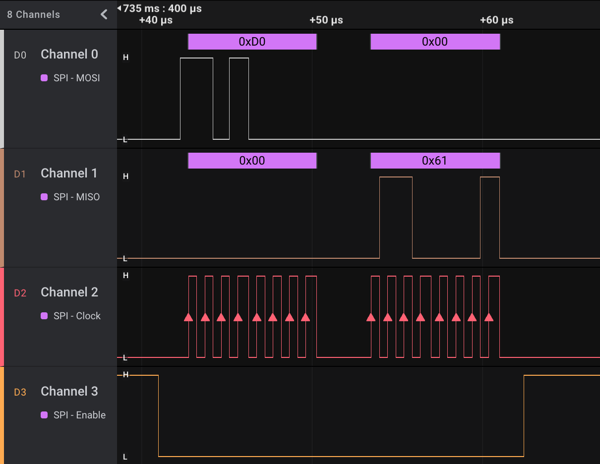
SPI Enable pin is pulled low by ESP32 to indicate that BME680 sensor is now selected for communication. ESP32 transmits the register read code 0xD0, serially, over the MOSI pin. BME680 transmits value 0x61, a magic number stored in the register, to ESP32 over the MISO pin. Clock pin is used by ESP32 to signal when data is to be read or written to the bus.
SPI bus is full-duplex—data is simultaneously sent and received.